This information is provided free of charge by the Department of Industrial Relations
from its web site at www.dir.ca.gov. These regulations are for the
convenience of the user and no representation or warranty is made that the information
is current or accurate. See full disclaimer at https://www.dir.ca.gov/od_pub/disclaimer.html.
Subchapter 7. General Industry Safety Orders
Group 1. General Physical Conditions and Structures Orders
Article 4. Access, Work Space, and Work Areas
Group 1. General Physical Conditions and Structures Orders
Article 4. Access, Work Space, and Work Areas
§3277. Fixed Ladders.
(a) All fixed ladders shall be approved as defined in Section 3206 of the General Industry Safety Orders.
(b) Definitions.
Cage. A cage is a guard that may be referred to as a cage or basket guard, which is an enclosure that is fastened to the side rails of the fixed ladder or to the structure to encircle the climbing space of the ladder for the safety of the person who must climb the ladder.
Carrier. The track of a ladder safety system consisting of a flexible cable or rigid rail, which is secured to the ladder or structure by mountings.
Cleats. Cleats are ladder crosspieces of rectangular cross section placed on edge on which a person may step in ascending or descending.
Fastenings. A fastening is a device to attach a ladder to a structure, building, or equipment. Fixed, hinged, bearing, or slide-type fastenings may be used.
Fixed Ladder. A fixed ladder is a ladder permanently attached to a structure, building, or equipment. Ladders referred to in this code shall be construed to be fixed ladders.
Grab Bars. Grab bars are individual handholds placed adjacent to or as an extension above ladders for the purpose of providing access beyond the limits of the ladder.
Individual-Rung Ladder. An individual-rung ladder is a fixed ladder each rung of which is individually attached to a structure, building, or equipment.
Ladder. A ladder is an appliance usually consisting of two side rails joined at regular intervals by crosspieces called steps, rungs, or cleats, on which a person may step in ascending or descending.
Ladder Safety System. An approved assembly of components whose function is to arrest the fall of a user. The ladder safety system shall include the carrier and its associated attachment elements (brackets, fasteners, etc.), safety sleeve, full body harness and connectors, wherein the carrier is permanently attached to the climbing face of the ladder or immediately adjacent to the structure.
Pitch. Pitch is the included angle between the horizontal and the ladder, measured on the opposite side of the ladder from the climbing side.
Rail Ladder. A rail ladder is a fixed ladder consisting of side rails joined at regular intervals by rungs or cleats and fastened in full length or in sections to a building, structure, or equipment.
Railings. Railings when referred to in this section shall be any one or a combination of those railings defined in Section 3210.
Rungs. Rungs are ladder crosspieces on which a person may step in ascending or descending.
Safety Sleeve. The part of a ladder safety system consisting of the moving component with locking mechanism that travels on the carrier and makes the connection between the carrier and the full body harness.
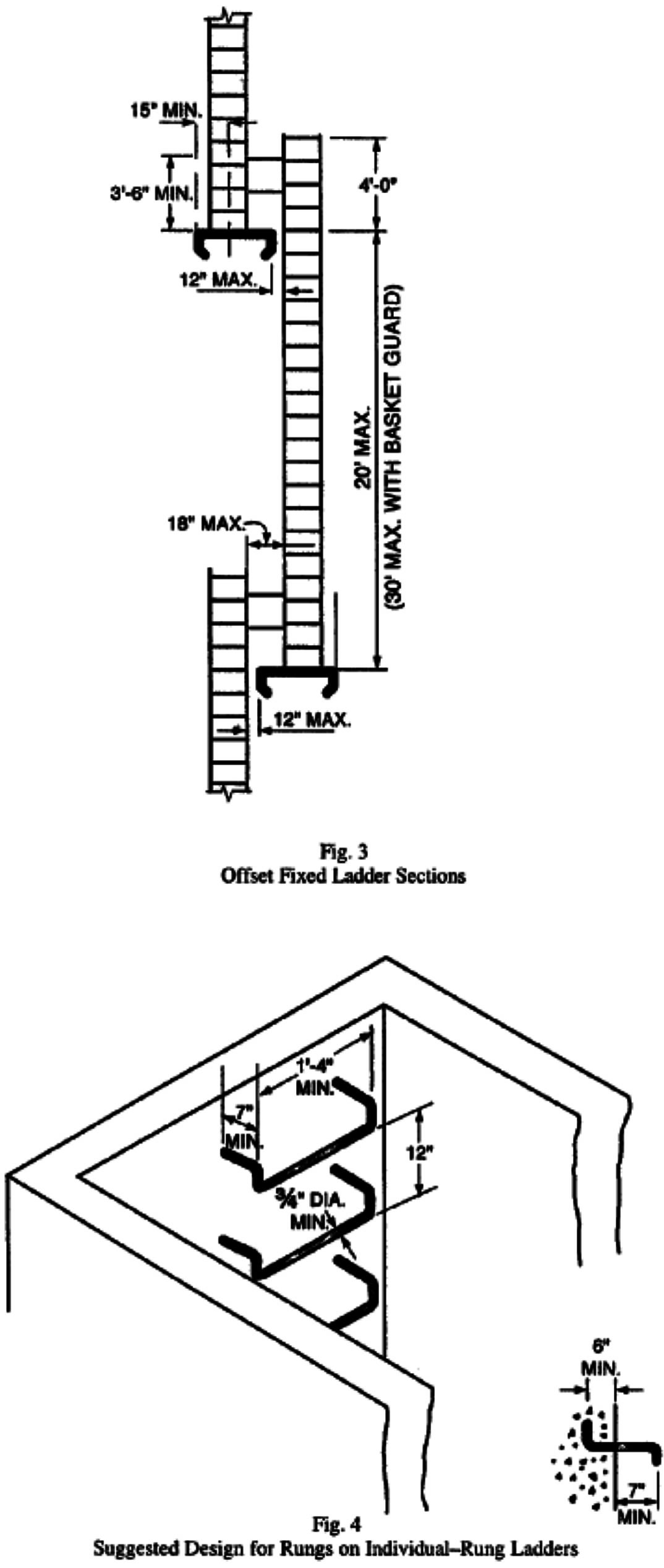
Side-Step Ladder. A side-step ladder is one from which a person getting off at the top must step sideways from the ladder in order to reach the landing, such as shown in Fig. 3.
Steps. Steps are the flat crosspieces of a ladder on which a person may step in ascending or descending.
Through Ladder. A through ladder is one from which a person getting off at the top must step through the ladder in order to reach the landing, such as shown in Fig. 2.
Well. A well is a permanent complete enclosure around a fixed ladder, which is attached to the walls of the well. Proper clearances for a well will give the person who must climb the ladder the same protection as a cage. (See (g)(6) and Fig. 1.)
(c) Design Considerations. All ladders, appurtenances, and fastenings shall be designed to meet the following load requirements:
(1) The minimum design live load shall be a single concentrated load of 200 pounds.
(2) The number and position of additional concentrated live-load units of 200 pounds each as determined from anticipated usage of the ladder shall be considered in the design.
(3) The live loads imposed by persons occupying the ladder shall be considered to be concentrated at such point or points as will cause the maximum stress in the structural member being considered.
(4) The weight of the ladder and attached appurtenances together with the live load shall be considered in the design of rails and fastenings.
(5) All wood parts of fixed ladders shall meet the design and construction requirements for portable wood ladders in Section 3276(c).
(6) For fixed ladders consisting of wood side rails and wood rungs or cleats, used at a pitch in the range 75 degrees to 90 degrees, and intended for use by no more than one person per section, single ladders or cleat ladders as described in Section 3276 are acceptable.
(d) Specific Features.
(1) All rungs shall have a minimum diameter of 3/4 inch for metal ladders, except as covered in (e)(1) and a minimum diameter of 1 1/8 inches for wood ladders. Materials other than steel, aluminum, and wood are acceptable provided the design, fabrication, and erection are in accordance with recognized design practice and meet the design requirements of Section 3277(c) and Section 3277(d)(11) when applicable.
(2) The distance between the top surfaces of rungs, cleats, and steps shall not exceed 12 inches and shall be uniform throughout the length of the ladder.
Exceptions:
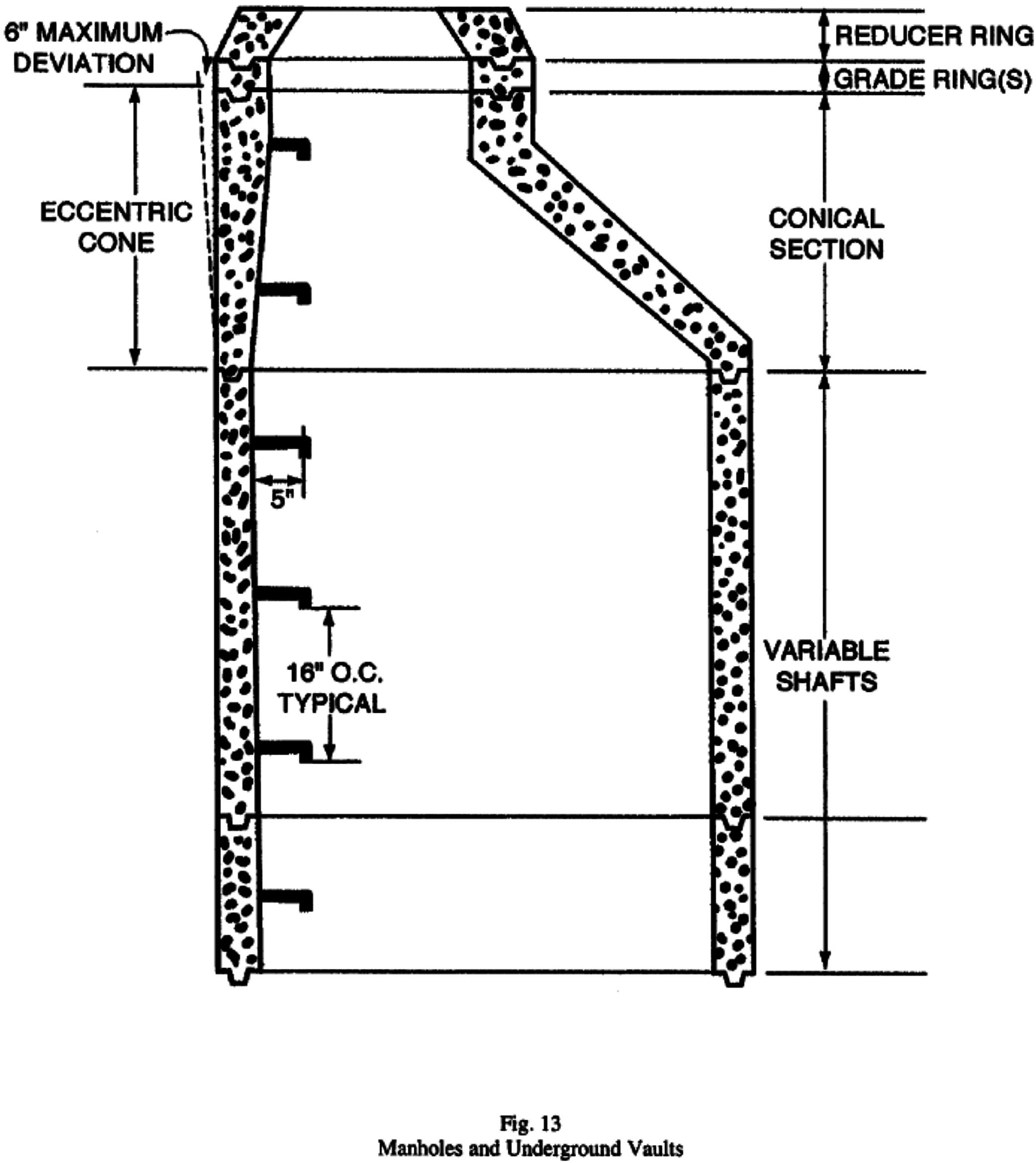
- 1. Manholes and Underground Vaults. Step spacing shall not exceed 16 inches between the top surfaces of rungs and shall be uniform throughout the length of the ladder.
- 2. The vertical distance of the first rung from ground level may be as high as 14 inches.
(3) The minimum clear length of rungs or cleats shall be 16 inches.
Exception:
- Manholes and Underground Vaults. Clear length of rungs or cleats shall not be less than 14 inches.
(4) Rungs, cleats, and steps shall be free of splinters, sharp edges, burrs, or projections which may be a hazard.
(5) The rungs of an individual-rung ladder shall be so designed that the climber's foot cannot slide off the end of a rung. A suggested design for metal rungs is shown in Fig. 4.
(6) Side Rails. Side rails which might be used as a climbing aid shall be of such cross sections as to afford adequate gripping surface without sharp edges, splinters, or burrs.
(7) Fastenings. Fastenings shall be an integral part of fixed ladder design.
(8) Splices. All splices made by whatever means shall meet design requirements as noted in (c). All splices and connections shall have smooth transition with original members and with no sharp or extensive projections.
(9) Electrolytic Action. Adequate means shall be employed to protect dissimilar metals from electrolytic action when such metals are joined.
(10) Welding. All welding shall be in accordance with procedures of the American Welding Society, or equivalent.
(11) Embedment. Individual rungs of ladders installed in manholes and underground vaults having a wall thickness which will not permit at least 6 inches of embedment shall have anchoring devices that will provide the minimum design load requirements of Section 3277(c) in addition to the following requirements:
(A) The minimum design live load shall be a single concentrated load of 300 pounds.
(B) Steps or rungs shall be embedded in the wall a minimum distance of 3 inches.
(e) Protection from Deterioration.
(1) Metal. Metal ladders and appurtenances shall be painted or otherwise treated to resist corrosion and rusting when location demands. Ladders formed by individual metal rungs imbedded in concrete, which serve as access to pits and to other areas under floors, are frequently located in an atmosphere that causes corrosion and rusting. To increase rung life in such atmosphere, individual metal rungs shall have a minimum diameter of 1 inch or shall be painted or otherwise treated to resist corrosion and rusting.
(2) Wood. Wood ladders, when used under conditions where decay may occur, shall be treated with a nonirritating preservative, and the details shall be such as to prevent or minimize the accumulation of water on wood parts. Wood ladders shall not be painted but may be coated with a clear sealant after inspection has assured that all requirements of 3278 have been met.
Note: Paint does not act as a wood preservative.
(3) Combined Materials. When different types of materials are used in the construction of a ladder, the materials used shall be so treated as to have no deleterious effect, one upon the other.
(f) Clearance.
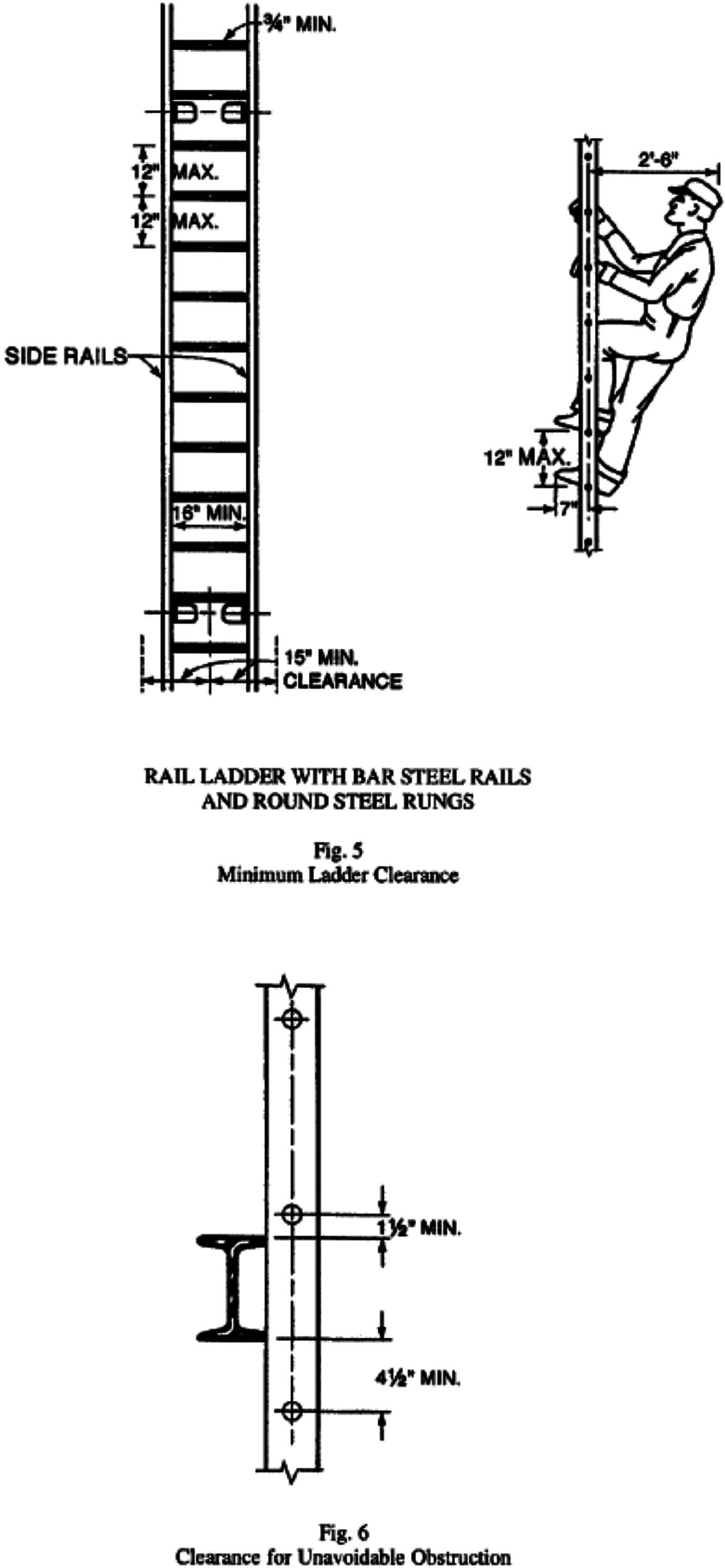
(1) On fixed ladders, the perpendicular distance from the center line of the rungs to the nearest permanent object on the climbing side of the ladder shall be 36 inches for a pitch of 76 degrees, and 30 inches for a pitch of 90 degrees (Fig. 5), with minimum clearances for intermediate pitches varying between these two limits in proportion to the slope, except as provided in (3) and (7).
Exception: Manholes and Underground Vaults.
(2) A clear width of at least 15 inches shall be provided each way from the center line of the ladder in the climbing space, except when cages or wells are necessary. (See (g)(2) and Fig. 5.)
Exception: Manholes and Underground Vaults.
(3) Ladders equipped with cage or basket shall be excepted from the provisions of (1) and (2), but shall conform to the provisions of (g)(5). Fixed ladders in smooth-walled wells shall be excepted from the provisions of (1), but shall conform to the provisions of (g)(6).
(4) The distance from the center line of rungs, cleats, or steps to the nearest permanent object in back of the ladder shall be not less than 7 inches (Fig. 5), except that when unavoidable obstructions are encountered, minimum clearances as shown in Fig. 6 shall be provided.
Exceptions:
- Manholes and Underground Vaults. The clearance from the center line of rungs or steps shall not be less than 5 inches.
- Obstructions. At those locations where unavoidable obstructions are encountered, minimum clearances shall be as shown in Figure 6.
(5) The distance from the center line of the grab bar to the nearest permanent object in back of the grab bars shall be not less than 4 inches. Grab bars shall not protrude on the climbing side beyond the rungs of the ladder which they serve.
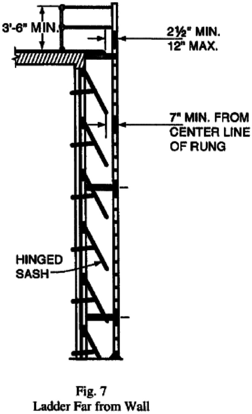
(6) The step-across distance from the nearest edge of ladder to the nearest edge of equipment or structure shall be not more than 12 inches, or less than 2 1/2 inches (Fig. 7).
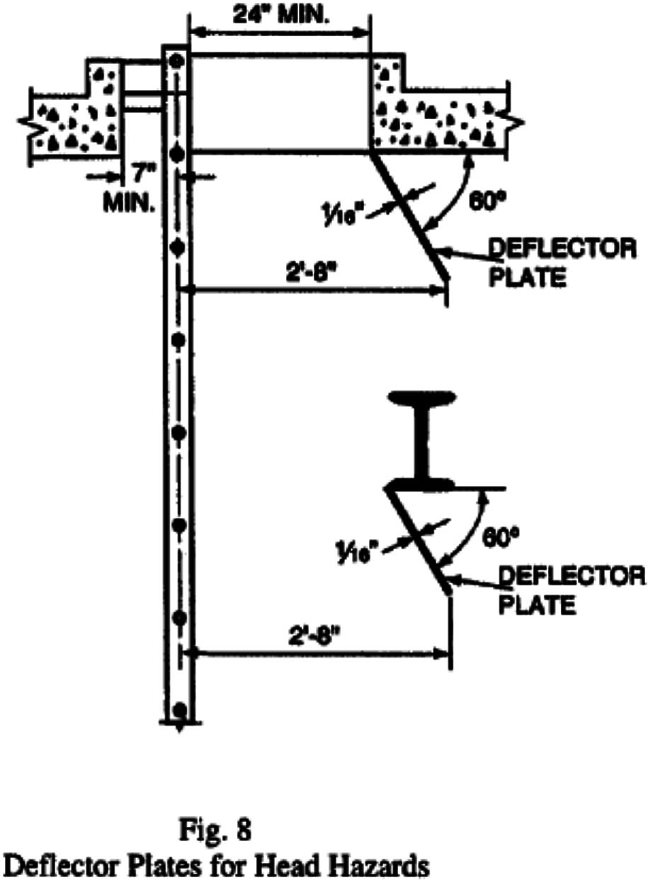
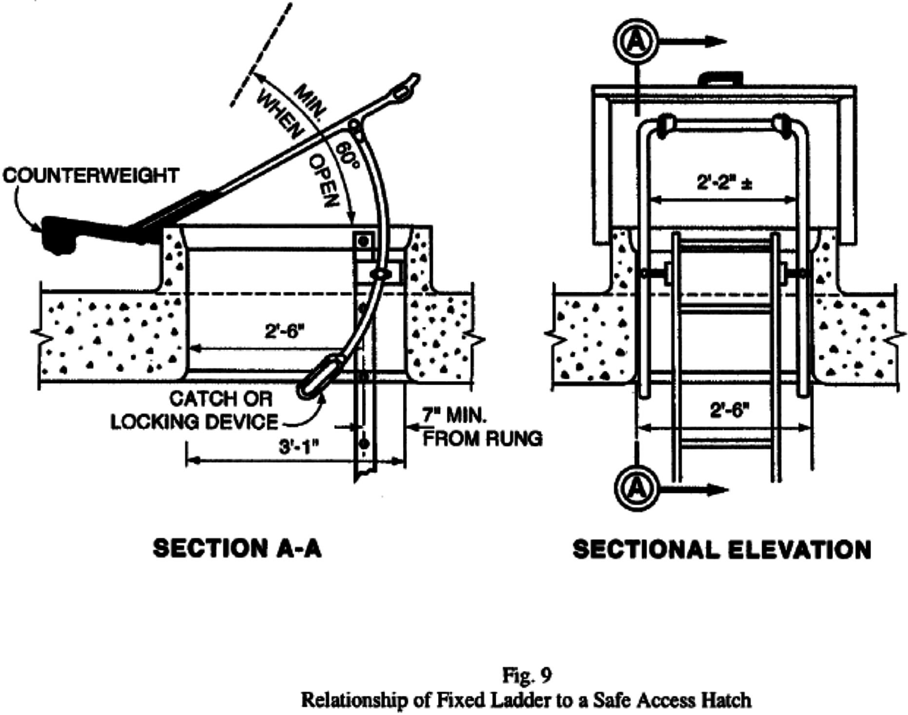
(7) All hatch covers shall open a minimum of 60 degrees from the horizontal. The distance from the center line of rungs or cleats to the edge of the hatch opening on the climbing side shall be not less than 24 inches for offset wells or 30 inches for straight wells. There shall be no protruding potential hazards within 24 inches of the center line of rungs or cleats; any such hazards within 30 inches of the center line of the rungs or cleats shall be fitted with deflector plates placed at an angle of 60 degrees from the horizontal as indicated in Fig. 8. The relationship of a fixed ladder to an acceptable hatch cover is illustrated in Fig. 9.
(g) Cages or Wells.
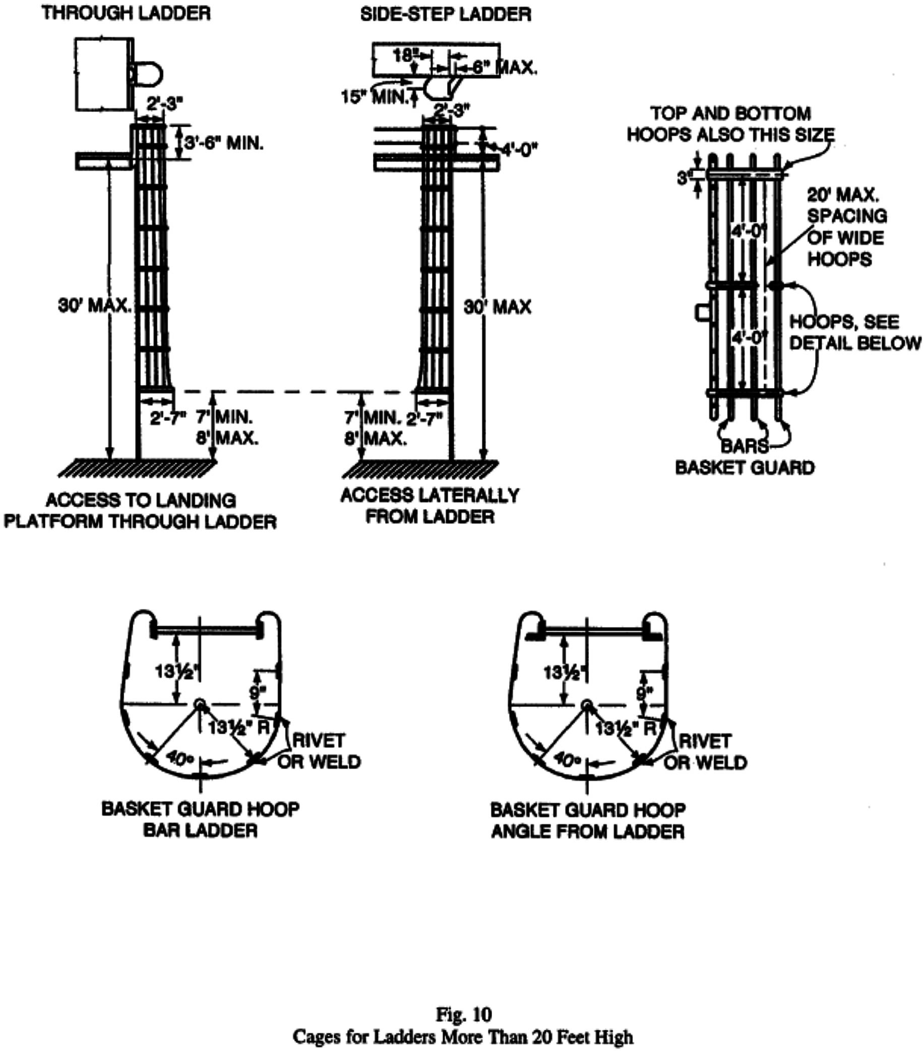
(1) Construction. Cages or wells shall be built as shown on the applicable drawings, covered in detail in Figs. 1, 10, and 11, or of equivalent construction.
Exception: Chimney ladders and manholes and underground vaults.
(2) Dimensions and Maximum Length. Cages or wells conforming to the dimensions shown in Figs. 1, 10, and 11 shall be provided on ladders of more than 20 feet to a maximum unbroken length of 30 feet.
Exceptions:
- Fixed ladders on fire hose drying towers are not required to have a cage, well, offset platform, or ladder safety device if they do not exceed 30 feet in length and provided their use is restricted to trained fire fighters or others equally trained in ladder use.
- Fixed ladders on outdoor advertising structures covered by Article 11.
- Ladders equipped with ladder safety systems as provided under subsection (m).
(3) Top of Cage. Cages shall extend a minimum of 42 inches above the top of landing, unless other acceptable protection is provided.
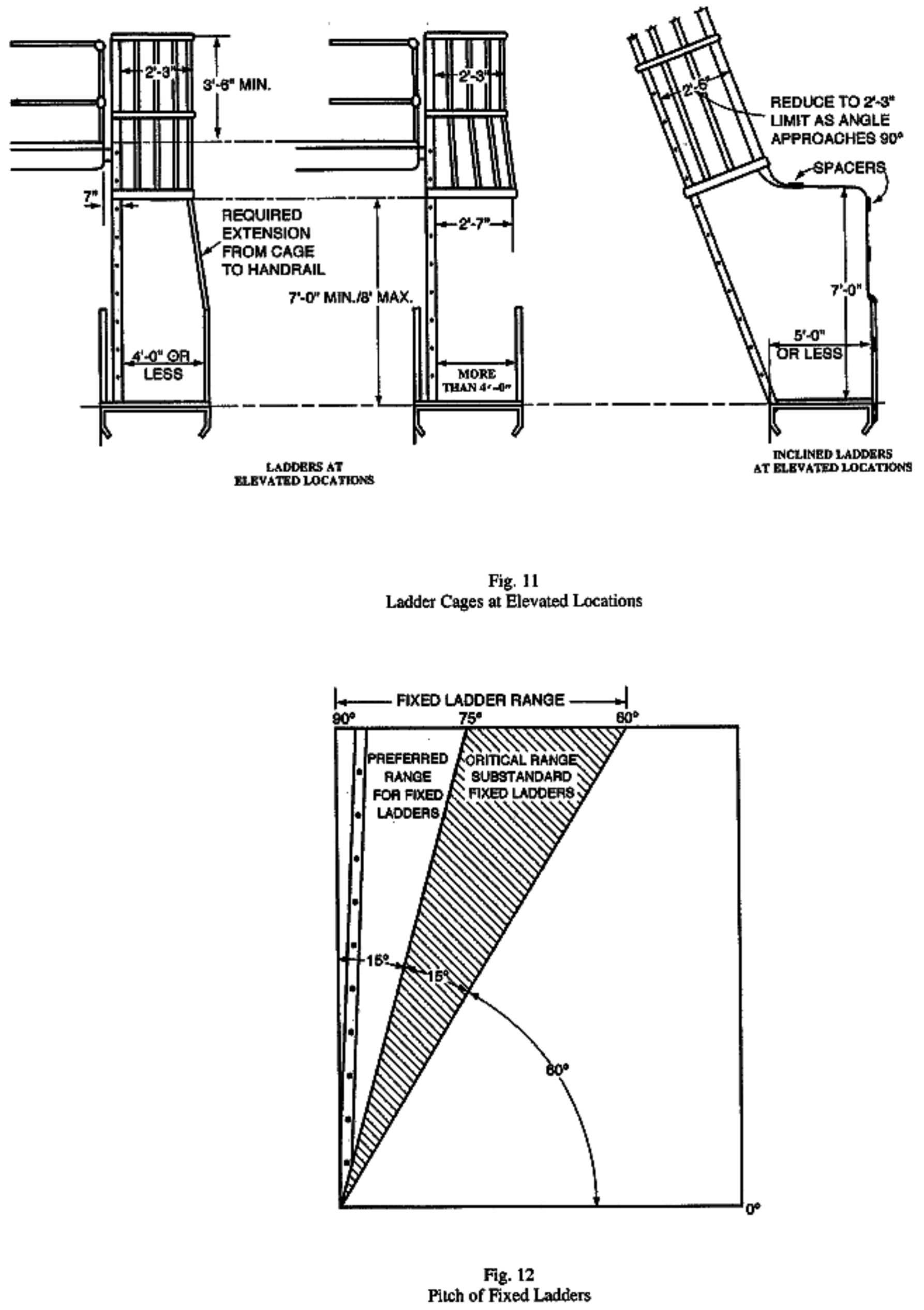
(4) Bottom of Cage. Cages shall extend down the ladder to a point not less than 7 feet nor more than 8 feet above the base of the ladder, with the bottom flared not less than 4 inches. When the ladder terminates on a landing platform or walkway at an elevation greater than 30 inches above the ground, a ladder cage extension shall be provided from the bottom of the cage to the top of the guardrail when the distance from the plane of the ladder rungs to the guardrail is equal to or less than that shown in Figure 11, "Ladder Cages at Elevated Locations."
(A) When the guardrail is located at a distance greater than that shown in Figure 11, a ladder cage extension need not be provided.
(B) The ladder cage extension or equivalent shall be constructed as follows:
1. The ladder cage extension or equivalent shall be capable of withstanding a force of at least 200 pounds applied horizontally at any point.
2. The ladder cage extension or equivalent shall be of solid construction, grille work with vertical bars located at a maximum spacing of 9-1/2 inches, center-to-center, or of slat-work with openings between slats not more than 4 vertical inches.
3. The ladder cage extension or equivalent shall be free of hazardous projections.
4. The ladder cage extension or equivalent shall be provided not less than two feet each side of the ladder center line where there is an exposure.
5. Vertical guardrail extensions may be used as equivalent construction for the ladder cage extension provided they are as high as the bottom of the cage opening and they comply with the provisions of (g)(4)(B).
(5) Size of Cage. Cages shall not extend less than 27 nor more than 30 inches from the center line of the rungs of the ladder. The cage shall not be less than 27 inches in width. The inside shall be clear of projections. Vertical bars shall be located at a maximum spacing of 9-1/2 inches, center-to-center around the circumference.
(6) Ladder Wells. Ladder wells shall have a clear width of at least 15 inches measured each way from the center line of the ladder. (See Fig.1.) Smooth-walled wells shall be a minimum of 27 inches and a maximum of 30 inches from the center line of rungs to the well wall on the climbing side of the ladder. Where other obstructions on the climbing side of the ladder exist, there shall be a minimum of 30 inches from the center line of the rungs.
(h) Pitch.
(1) Preferred Pitch. The preferred pitch of fixed ladders shall be considered to come in the range of 75 to 90 degrees with the horizontal. (See Fig. 12.)
(2) Substandard Pitch. Fixed ladders shall be considered as substandard if they are installed within the substandard pitch range of 60 to 75 degrees with the horizontal. Substandard fixed ladders shall be permitted only where it is found necessary to meet conditions of installation. (See Fig. 12.) This substandard pitch range shall be considered as a critical range to be avoided, if possible.
(3) Scope of Coverage in This Code. This code covers only fixed ladders within the pitch range of 60 to 90 degrees with the horizontal. (See Fig. 12.)
(4) Pitch Greater Than 90 Degrees. Ladders having a pitch in excess of 90 degrees with the horizontal shall not be permitted.
Exception: Manholes and Underground Vaults. Individual rung ladders installed in the walls of conical top sections of manholes and underground vaults shall be allowed to exceed a pitch of 90 degrees for a distance of not more than 2 rungs or steps in the conical top sections. The deviation from 90 degrees shall not exceed 6 inches. (See Figure 13.)
(i) Maintenance. All ladders shall be maintained in a safe condition. All ladders shall be inspected regularly, with the intervals between inspections being determined by use and exposure.
(j) Landing Platforms.
(1) When ladders are used to ascend to heights exceeding 20 feet, landing platforms shall be provided as follows:
(A) Where no cage, well, or ladder safety system is provided, landing platforms shall be provided for each 20 feet of height or fraction thereof.
(B) Where a cage or well is provided and no ladder safety system is provided, landing platforms shall be provided for each 30 feet of height or fraction thereof.
(C) Each ladder section shall be offset from adjacent ladder sections at each landing.
(D) Where installation conditions (even for a short, unbroken length) require that adjacent sections be offset, landing platforms shall be provided at each offset [See Subsection (m)].
Exceptions to subsection (j)(1):
- 1. Ladders used primarily in construction operations, fire escape ladders, and ladders equipped with treads.
- 2. Ladders on high-voltage transmission towers, chimneys, smoke stack ladders, water tower ladders and similar fixed ladders on permanent installations which are used either infrequently or for emergency only, provided the employee who uses the ladder is supplied with and wears approved personal fall protection equipment, which can be utilized if a rest period is required.
- 3. Ladders in underground mines as covered by the Mine Safety Orders.
(2) Where an employee has to step a distance greater than 12 inches from the center line of the rung of a ladder to the nearest edge of structure or equipment, a landing platform shall be provided. The minimum step-across distance shall be 2 1/2 inches (Figure 7).
(3) All landing platforms shall be equipped with guardrails and toeboards, so arranged as to give safe access to the ladder. Platforms shall be not less than 24 inches in width and 30 inches in length.
(4) One rung of any section of ladder shall be located at the level of the landing laterally served by the ladder. Where access to the landing is through the ladder, the same rung spacing as used on the ladder shall be used from the landing platform to the first rung below the landing (Figure 10).
(k) Ladder Extensions. The side rails of through or side-step ladder extensions shall extend 3 1/2 feet above parapets and landings. For through ladder extensions, the rungs shall be omitted from the extension and shall have not less than 18 nor more than 24 inches clearance between rails (Figure 2). For side-step or offset fixed ladder sections, at landings, the side rails and rungs shall be carried to the next regular rung beyond or above the 3 1/2 feet minimum (Figure 3).
(l) Grab Bars. Grab bars shall be spaced by a continuation of the rung spacing when they are located in the horizontal position. Vertical grab bars shall have the same spacing as the ladder side rails. Grab bar diameters shall be the equivalent of the round-rung diameters.
(m) Ladder Safety Systems. Ladder safety systems may be used on tower, water tank, and chimney ladders over 20 feet in unbroken length in lieu of cage protection. No landing platform shall be required in these cases. All ladder safety systems shall meet the design requirements of the ladders which they serve [See subsection (c)].
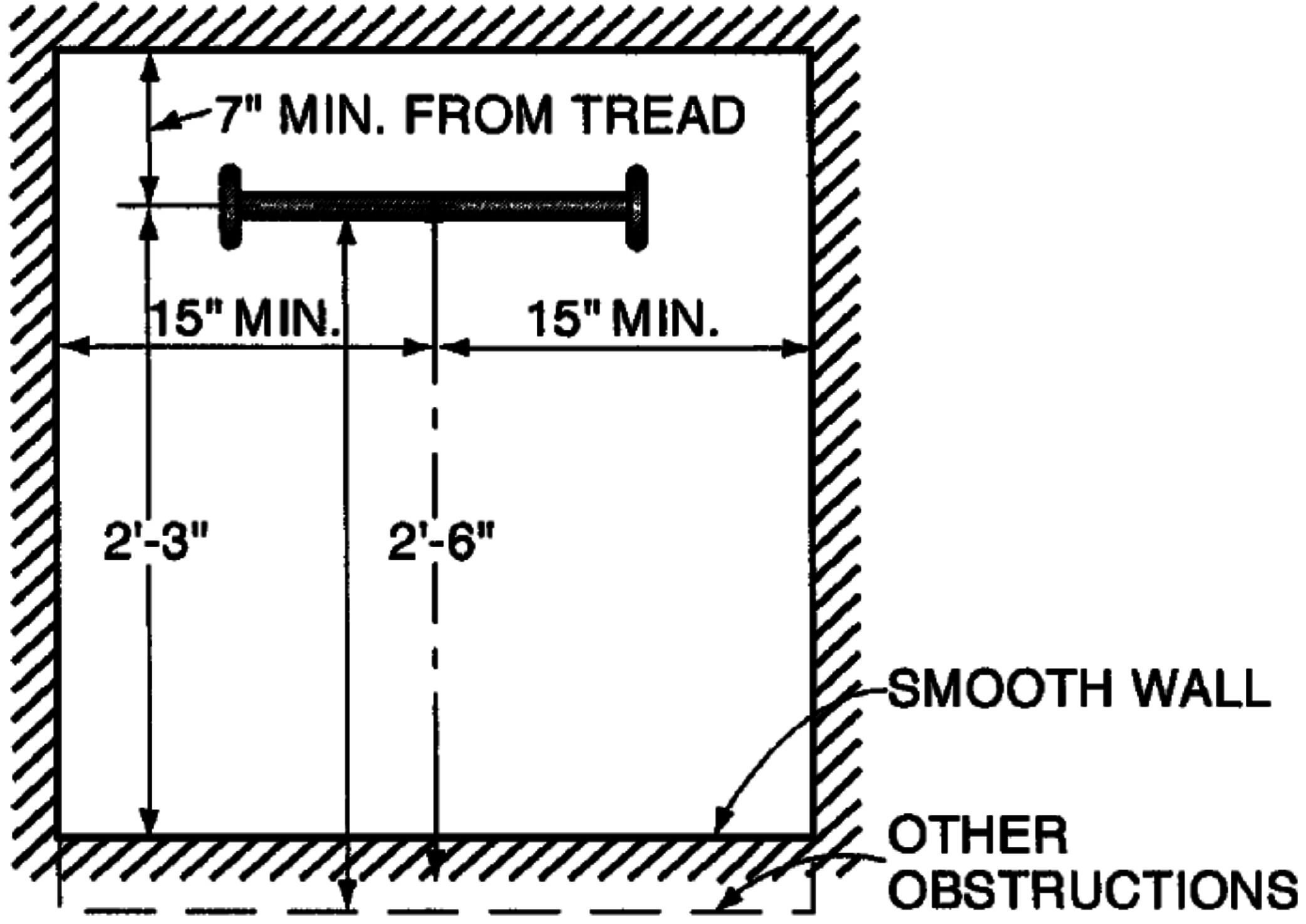
Fig. 1: Clearance Diagram for Fixed Ladder in Well
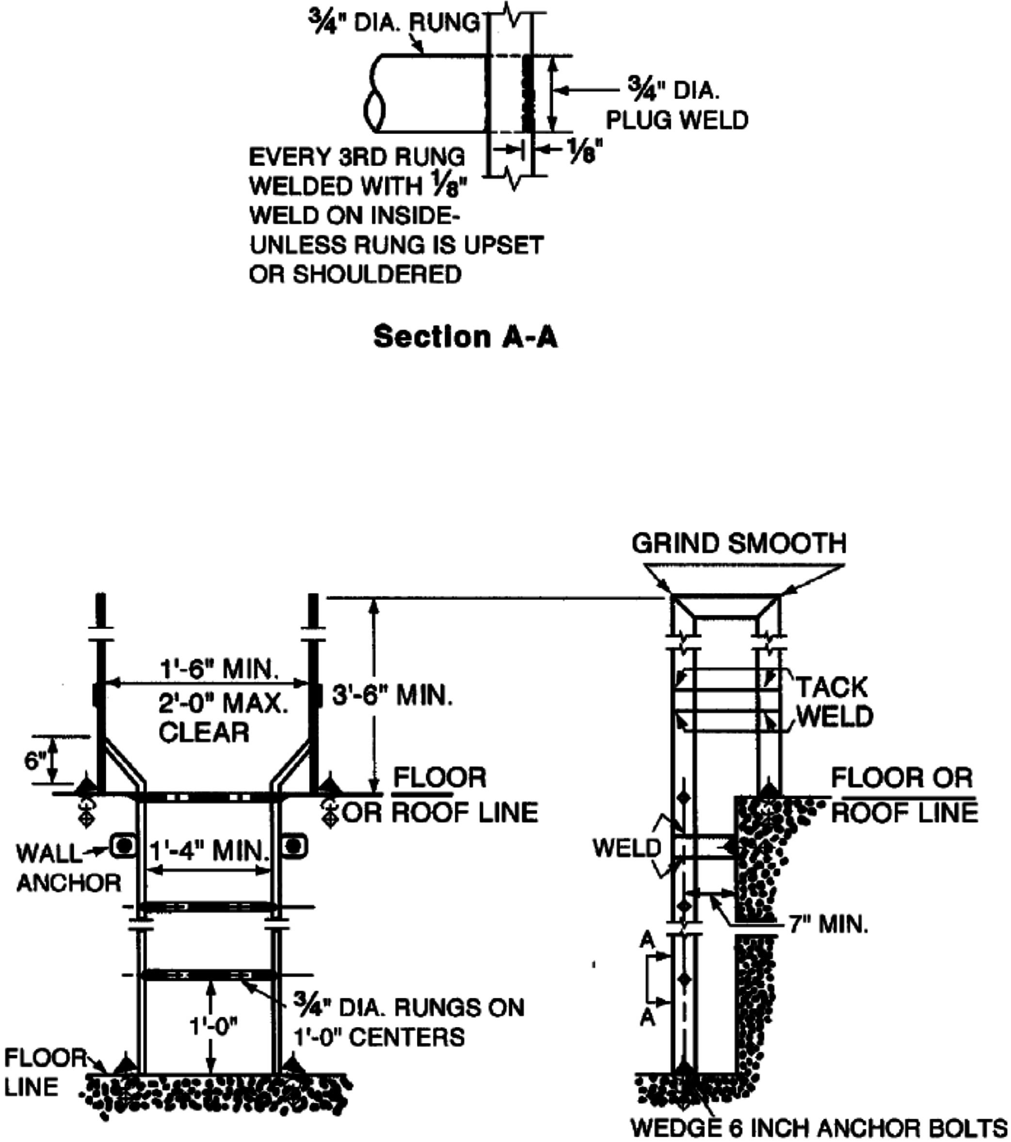
Fig. 2: Roof Ladder
Note: Authority cited: Section 142.3, Labor Code. Reference: Section 142.3, Labor Code.
HISTORY
1. Amendment of subsections (b)(14), (e)(2), (f)(1), (f)(2) and (g)(1) filed 6-20-75; effective thirtieth day thereafter (Register 75, No. 25).
2. Amendment of subsection (g)(5) filed 9-12-75 as an emergency; effective upon filing (Register 75, No. 37).
3. Amendment of subsection (g)(5) filed 1-2-76; effective thirtieth day thereafter (Register 76, No. 1).
4. Amendment filed 7-16-76; effective thirtieth day thereafter (Register 76, No. 29).
5. Amendment of subsection (g)(2) filed 7-26-78; effective thirtieth day thereafter (Register 78, No. 30).
6. Amendment of subsections (d), (f)(4) and (h)(4) filed 10-29-80; effective thirtieth day thereafter (Register 80, No. 44).
7. Amendment of Figure 4 filed 10-29-80; effective thirtieth day thereafter (Register 80, No. 44).
8. New Figure 13 filed 10-29-80; effective thirtieth day thereafter (Register 80, No. 44).
9. Editorial correction of subsection (d)(11) filed 1-23-81; effective thirtieth day thereafter (Register 81, No. 4).
10. Repealer of subsections (g)(7)-(g)(13) and new subsections (j)-(m) filed 1-23-81; effective thirtieth day thereafter (Register 81, No. 4).
11. Editorial correction of subsection (j)(1) (Register 81, No. 46).
12. Editorial correction of subsection (j) (Register 82, No. 11).
13. Amendment filed 2-26-85; effective thirtieth day thereafter (Register 85, No. 9).
14. Amendment of Figure 13 filed 2-26-85; effective thirtieth day thereafter (Register 85, No. 9).
15. Amendment of subsection (a) filed 6-1-92; operative 7-1-92 (Register 92, No. 23).
16. Editorial correction renumbering second labeled figure 6 to 7 and third labeled figure 6 to 8 (Register 92, No. 33).
17. Editorial correction repositioning History notes (Register 92, No. 33).
18. Amendment of subsection (d)(2) Exception and Note filed 7-30-96; operative 8-29-96 (Register 96, No. 31).
19. Amendment of subsection (a) filed 3-19-99; operative 4-18-99 (Register 99, No. 12).
20. Change without regulatory effect providing more legible figures 1-13 filed 2-9-2009 pursuant to section 100, title 1, California Code of Regulations (Register 2009, No. 7).
21. Amendment of section, figure 11 and Note filed 10-22-2009; operative 11-21-2009 (Register 2009, No. 43).
22. Amendment of subsections (c)(5)-(6) filed 12-8-2010; operative 1-7-2011 (Register 2010, No. 50).
![]() Go Back to Article 4 Table of Contents
Go Back to Article 4 Table of Contents