Article 22. Scaffolds--Various Types
| Return to index New query |
§1644. Metal Scaffolds.
(a) General.
(1) Metal scaffolds shall be designed to support all dead, live, and wind loads to which they will be subjected.
(2) No metal scaffold equipment that is broken or deteriorated to the extent that its section is structurally weakened shall be used.
(3) All stationary scaffold legs, including those of outriggers, shall rest upon base plates available from the manufacturer for this service. Each base plate shall have support adequate to sustain the load and prevent horizontal movement. When the scaffold or outrigger is resting on earth or soft material, the base plate shall rest on and be secured to the equivalent of a 2-inch by 10-inch by 10-inch wooden base.
Note: A 1 1/8-inch by 10-inch by 10-inch piece of exterior grade plywood may be used in lieu of the wooden base mentioned above.
(4) Platform planks shall not be placed on guardrails to obtain greater height.
(5) Metal scaffolds shall be securely tied to the building or structure by means of a double looped No. 12 iron wire, or single looped No. 10 iron wire or equivalent at intervals not to exceed 30 feet horizontally and subject to the following:
(A) Ties shall be required at the free ends of the scaffold when the height of the scaffold platform exceeds 3 times the least base dimension. The remaining ties of the first row shall be required when the height of the scaffold platform is four times the least base dimensions.
(B) Ties for subsequent levels shall be installed at 26-foot intervals vertically, with the last tie no further from the top than four times the least base dimension.
(C) As an alternate means, scaffolds shall be guyed or outriggers shall be used to prevent tipping or upsetting.
(D) Wind Loading. When scaffolds are partially or fully enclosed, specific precautions shall be taken to assure the frequency and adequacy of ties attaching the scaffolding to the building.
(6) Securely attached railings as provided by the scaffold manufacturer, or other material equivalent in strength to the standard 2- by 4-inch wood railing made from "selected lumber" (see definition), shall be installed on open sides and ends of work platforms 7 1/2 feet or more above grade. The top rail shall be located at a height of not less than 42 inches nor more than 45 inches measured from the upper surface of the top rail to the platform level. A midrail shall be provided approximately halfway between the top rail and the platform.
Note: Toeboards or side screens may also be required. (See Section 1621.)
(A) "X" bracing is acceptable as a toprail if the intersection of the "X" occurs at 45 inches (plus or minus 3 inches) above the work platform, provided a horizontal rail is installed as a midrail between 19 and 25 inches above the work platform. The maximum vertical distance between the "X" brace members at the uprights shall not exceed 48 inches.
(B) "X" bracing is acceptable as a midrail if the intersection of the "X" falls between 20 inches and 30 inches above the work platform.
Exceptions:
(1) Railings are not required on that side of bricklayers' and masons' scaffold adjacent to the work under construction provided the wall is higher than the adjacent work platform.
(2) For end rail openings less than 3 feet, double wrapped iron wire at least No. 12 gauge in thickness, or wire rope at least 1/4 inch minimum diameter is permitted, provided the wire or wire rope is securely fastened.
(7) Platform planks shall be of 2-inch by 10-inch or wider material and of such length that they overlap the ledgers at each end by at least 6 inches.
A plank shall not overlap an unsupported end of another plank.
The working platform shall cover the entire space between scaffold uprights, except for the open area under the back railing. Such open area shall not exceed 10 inches in width.
The inboard edge of the work platform shall be no more than 16 inches from the building or structure wall except for those scaffolds used by bricklayers and stonemasons the platforms of which shall extend to within 7 inches of the finish face of the building or structure on which the work is being performed.
(8) All ladders used for access shall conform to ladders, Article 25. When only a part of the width of the metal scaffold frame conforms to ladder spacing, then these frames must be erected in a manner that makes a continuous ladder bottom to top, with ladder sides of the frames in a vertical line.
(b) Tube and Coupler Scaffolds.
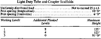
(1) A light duty tube and coupler scaffold shall have all posts, ledgers, ribbons and bracing of nominal 2-inch O. D. steel tubing. The posts shall be spaced no more than 6 feet apart by 10 feet along the length of the scaffold. Other structural metals when used must be designed to carry an equivalent load. No dissimilar metals shall be used together.
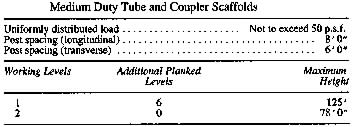
(2) A medium duty tube and coupler scaffold shall have all posts, ribbons and bracing of nominal 2-inch O. D. steel tubing. Posts spaced not more than 6 feet apart by 8 feet along the length of the scaffold shall have ledgers of nominal 2 1/2-inch O. D. steel tubing. Posts spaced not more than 5 feet apart by 8 feet along the length of the scaffold shall have ledgers of nominal 2-inch O. D. steel tubing. Other structural metals, when used, must be designed to carry an equivalent load. No dissimilar metals shall be used together.
(3) A heavy duty tube and coupler scaffold shall have posts, ribbons, and bracing of nominal 2-inch O. D. steel tubing, with the posts spaced not more than 6 feet by 6 feet 6 inches. Other structural metals, when used, must be designed to carry an equivalent load. No dissimilar metals shall be used together.
(4) Tube and coupler scaffolds shall be limited in heights and working levels to those permitted in Tables 1, 2, and 3. Drawings and specifications of all tube and coupler scaffolds above the limitations in Tables 1, 2, and 3 shall be designed by a Civil Engineer currently registered in the State of California.
(5) All tube and coupler scaffolds shall be constructed and erected to support 4 times the maximum intended loads as set forth in Tables 1, 2, and 3, or as set forth in the specifications by a Civil Engineer currently registered in California.
Table 1

Image 1 (1.5" X 3.5") Not available for Offline Print to STP or FAX
Table 2

Image 2 (1.5" X 3.75") Not available for Offline Print to STP or FAX
Table 3

Image 3 (1.25" X 3.75") Not available for Offline Print to STP or
FAX
(6) Posts shall be accurately spaced, erected on suitable bases, and maintained
plumb.
(7) Ribbons shall be erected along the length of the scaffold, located on both the inside and the outside posts at even height. Ribbons shall be interlocked to the inside and the outside posts at even heights. Ribbons shall be interlocked to form continuous lengths and coupled to each post. The bottom ribbons shall be located as close to the base as possible. Ribbons shall be placed not more than 6 feet 6 inches on centers.
(8) Ledgers shall be installed transversely between posts and shall be securely coupled to the posts bearing on the ribbon coupler. When coupled directly to the ribbons, the coupler must be kept as close to the posts as possible.
(9) Ledgers shall be at least 4 inches but not more than 12 inches longer than the post spacing or ribbon spacing.
(10) Cross bracing shall be installed across the width of the scaffold at least every third set of posts horizontally and every fourth ribbon vertically. Such bracing shall extend diagonally from the inner and outer ribbons upward to the next outer and inner ribbons.
(11) Longitudinal diagonal bracing on the inner and outer rows of poles shall be installed at approximately a 45 degree angle from near the base of the first outer post upward to the extreme top of the scaffold. Where the longitudinal length of the scaffold permits, such bracing shall be duplicated beginning at every fifth post. In a similar manner, longitudinal diagonal bracing shall also be installed from the last post extending back and upward toward the first post. Where conditions preclude the attachment of this bracing to the posts, it may be attached to the ribbons.
(c) Tubular Welded Frame Scaffolds.
(1) Metal tubular frame scaffolds, including accessories such as braces, brackets, trusses, screw legs, ladders, etc., shall be designed, constructed, and erected to safely support four times the maximum rated load. The scaffold manufacturer's erection instructions shall be followed on all installations.
(2) Spacing of panels or frames shall be consistent with the loads imposed.
(3) Panels or frames shall be braced by horizontal bracing, cross bracing, diagonal bracing or any combination thereof for securing vertical members together laterally, and the cross braces shall be of such length as will automatically square and align vertical members so that the erected scaffold is always plumb, square, and rigid. All brace connections shall be made secure.
(4) Panel or frame legs shall be set on adjustable bases or plain bases placed on mud sills or other foundations adequate to support the maximum anticipated load.
(5) Panels or frames shall be placed one on top of the other with coupling or stacking pins to provide proper vertical alignment of the legs.
Note: Where an intervening ledge prevents the vertical stacking of legs, the ledge may be used as a base provided that an equally safe installation is obtained.
(6) Where uplift may occur, panels shall be locked together vertically by pins or other equivalent suitable means.
(7) Drawings and specifications for all frame scaffolds over 125 feet in height above the base plates shall be designed by a Civil Engineer currently registered in California.
<General Materials (GM) - References, Annotations, or Tables>
Note: Authority cited: Section 142.3, Labor Code. Reference: Section 142.3,
Labor Code.
HISTORY
1. Repealer and new section filed 11-14-75; effective thirtieth day thereafter
(Register 75, No. 46).
2. Amendment of subsection (a)(6) filed 8-3-76 as an emergency; effective upon
filing (Register 76, No. 32).
3. Certificate of Compliance filed 10-8-76 (Register 76, No. 41).
4. Amendment filed 3-19-79; effective thirtieth day thereafter (Register 79,
No. 12).
5. Amendment of subsection (a)(5) filed 9-5-79; effective thirtieth day
thereafter (Register 79, No. 36).
6. Amendment of subsections (a)(4) and (a)(5) filed 1-17-80; effective
thirtieth day thereafter (Register 80, No. 3).
7. Amendment of subsection (a)(7) filed 10-5-81; effective thirtieth day
thereafter (Register 81, No. 41).
8. Amendment filed 7-24-87; operative 8-23-87 (Register 87, No. 33).
9. Amendment of subsection (a)(6) Exceptions filed 10-28-98; operative 11-27-
98 (Register 98, No. 44).
10. Amendment of subsection (a)(6)(B) filed 2-28-2006; operative 3-30-2006
(Register 2006, No. 9).
 Go Back to Article 22 Table of Contents