Acceptance Tests for Plastic Piping
The following are tests that shall be passed for acceptance of plastic piping for the conveyance of compressed air:
1. Test for impact resistance at 0oC: (32oF)
Objective: To determine if the material will withstand the energy of impact
without fracturing through the complete wall thickness.
Form of test specimen: Each specimen shall be a section of pipe, of a length equal to twice the nominal size or 150 mm (6" ), whichever is greater, subject to a maximum length of 300 mm (12" ). The ends of the specimen shall be cut clean and equal to the axis of the pipe.
For "round-the-clock" testing, each specimen shall be marked with the number of longitudinal lines shown in Table 1.
Note: For pipe sizes 50 mm (2 " ) and over, specimens are subjected to impact equally spaced around the pipe; this procedure is known as "round-the-clock" testing.
Apparatus: A falling weight machine (an example of which is shown in Figure 1) shall be used and shall consist essentially of the following:
| | a. A main frame which can be rigidly fixed in a true vertical position. | |
| | b. Guide rails, carried from the inside of the main frame, on side bearings which can be adjusted to keep them parallel and vertical. | |
| | c. A weighted striker that can fall freely within the guide rails and that is equipped with a hardened hemispherical striking surface 25 mm (1" ) in diameter. The striking surface shall be free from flats and/or other imperfections. | |
| | d. An appropriate set of weights which can be firmly attached to the striker to enable the combined weight to be adjusted to the values shown in Table 2. | |
| | Procedure: Adjust the total energy of the striker to the value appropriate to the pipe diameter being tested as shown in Table 2. | |
| | Condition each specimen in a water or ethylene glycol bath for at least one hour prior to the test at a temperature of 0oC (32oF) + 1o. Test individual specimens within 10 seconds of removal from the bath. allow the striker to fall freely onto the pipe specimen, which is centrally mounted on the vee block support. | |
| | Specimens from 10 mm (3/8" ) to 38 mm (1-1/2" ) (inclusive) nominal size shall be subjected to a single strike only. | |
| | For pipe size 50 mm (2" ) and above. Place the pipe on the vee block, so that one of the marked lines is uppermost. Then allow the weight striker to fall freely on the marked line on the pipe as described above. If the specimen does not fail as a result of cracking or splitting through the pipe wall, rotate the specimen until the next marked line is uppermost in the vee block, and cause a second blow to be made by the striker. Repeat the process until all the marked lines have been tested, or until a failure is recorded. | |
| | If the required sequence of impacts has not been completed within 10 seconds, interrupt the procedure and immediately recondition the specimen at a temperature of 0oC (32o F) + 1oFor at least 10 minutes. | |
| | Fracturing or cracking through the complete wall thickness of the test specimen shall be a failure. | |
| | The following tests (Nos. 2 & 3) are intended to simulate a potential destructive impact. Splitting through the pipe wall or puncture is acceptable for passing results, if: | |
| | (a) No separation of one part of piping length from its mating part occurs. | |
| | (b) No separation of any material fragment from the body of the piping occurs. | |
2. Test for impact resistance at design pressure at 0oC (32oF) with blunt striker. Testing procedures and apparatus shall be the same as Test No. 1, except:
| | (a) Pressurize and maintain pipe sample at design pressure and cool to 0oC (32oF) as in Test No. 1. | |
| | (b) Energy of the striker to be twice the total energy of Table 2. | |
| | (c) Only one drop required. | |
3. Test for impact resistance at design pressure at 0oC (32oF) with sharp striker. Same as Test No. 2 in all cases, except with a chisel edged sharp striker (Figure 2).
4. The plastic piping systems shall be capable of sustaining without failure at least 600 psi when tested to the Standard Test Method for Short-Time Hydraulic Failure Pressure of Plastic Pipe, Tubing, and Fittings, using ASTM Designation No. D1599-86 (1986) which is herein incorporated by reference. This test shall
be performed on each batch of pipe and fittings.
5. The plastic piping system shall be capable of sustaining without failure at least 460 psi when tested to the Standard Test Method for Time-to-Failure of Plastic Pipe Under Constant Internal Pressure using ASTM Designation No. D1598- 86 (1986), which is herein incorporated by reference, for at least 1,000 hours. This test shall be performed anytime there is a change in:
| | (a) material composition, compound or processing technique; | |
| | (b) design or size of joint or fitting; | |
| | (c) but, in any case not less than every 12 months. | |
Table 1.
Number of Lines For "Round-the-Clock" Testing
Number of Equidistant
Normal Size mm (inches) .. Lines to be Drawn
50 ......................... mm (2 3
63 ......................... mm (2-1/2 4
75 ......................... mm (3 4
100 ........................ mm (4 6
Table 2.
Energy of Striker
Total Energy
Normal Size of Pipe .. of Striker
mm (inches ..... ft. lbs.
10 ........................ mm (3/8 22
12 ........................ mm (1/2 33
19 ........................ mm (3/4 43
25 ........................ mm (1 54
38 ........................ mm (1-1/2 65
50 ........................ mm (2 76
63 ........................ mm (2-1/2 98
75 ........................ mm (3 98
100 ....................... mm (4 110
| | (c) Whenever an owner or user of any apparatus or equipment fails to pay the fees required under this section within 60 days after notification, said owner or user shall pay, in addition to the fees required under this section, a penalty fee equal to 100 percent of such fee. For the purpose of this section, the date of the invoice shall be considered the date of notification. | |
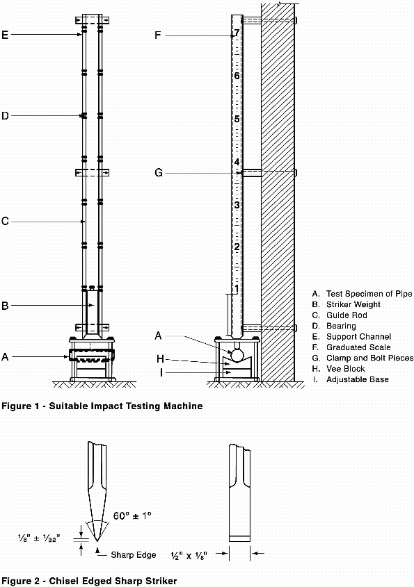 Image 1 (8.5" X 6") Not available for Offline Print to STP or FAX
<General Materials (GM) - References, Annotations, or Tables>
HISTORY
1. New Appendix C filed 3-28-78; effective thirtieth day thereafter (Register
78, No. 13).
2. Repealer and new Appendix C filed 4-8-92; operative 5-8-92 (Register 92,
No. 18).
3. Change without regulatory effect providing more legible illustrations filed
8-4-2008 pursuant to section 100, title 1, California Code of Regulations
(Register 2008, No. 32).
|